
This is another project building a single board computer with an Z80 MCU alongside some RAM and ROM. In contrast to other well known projects I want to utilise an EEPROM which is very easy to handle. I also want to build a computer that works autonomously including an user interface and does not need additional microcontroller or a PC since both would be more powerful than the actual processor.
It is inspired by the SBC project by Grant Searle and therefore runs his modified version of Microsoft BASIC for the NASCOM computer. I further modified it for this SBC.
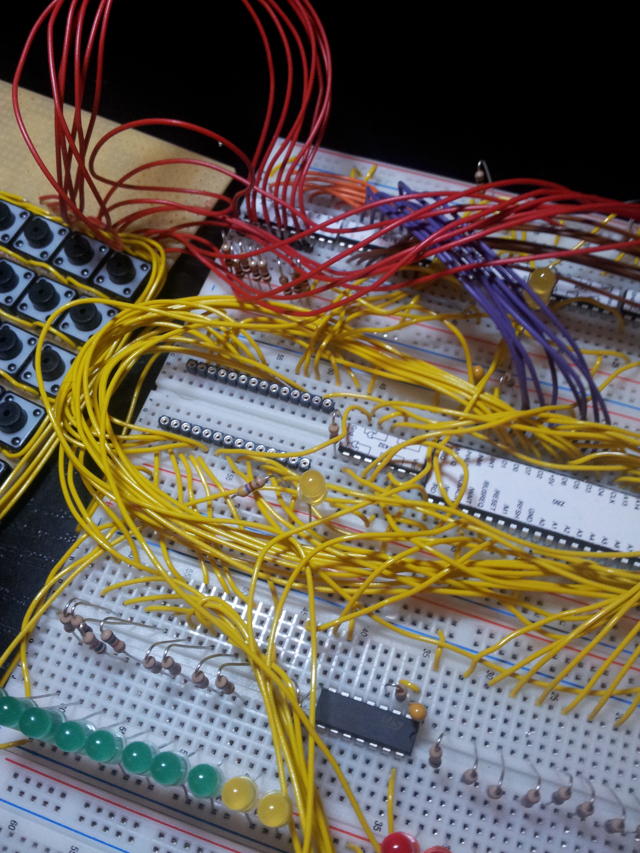
Before I explain the details, here is the result.
Table of Contents
Overview
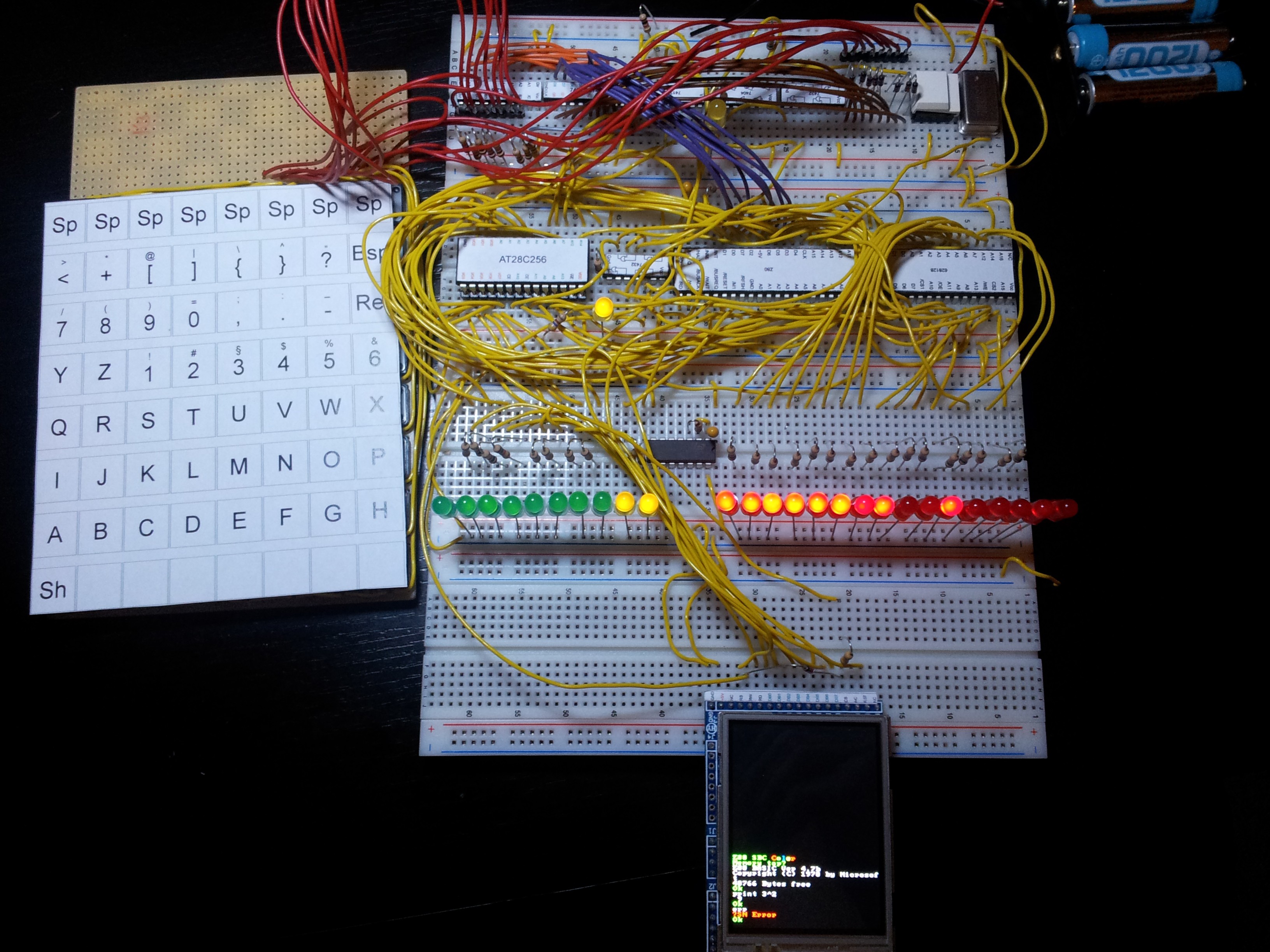
Z80 SBC overview
The specs are:
- MCU: Z80 in CMOS (Z84C006) at 7.3728 MHz
- RAM: 628128 SRAM
- ROM: AT28C256 EEPROM
- Display: 320×240 TFT with ILI9325 controller
- Keyboard with 64 keys
- Power consumption: 190 mA at 5V
- OS: NASCOM BASIC 4.7b
There is no serial or parallel I/O at the moment. Therefore BASIC listing cannot be loaded or saved.
Curcuit Diagram
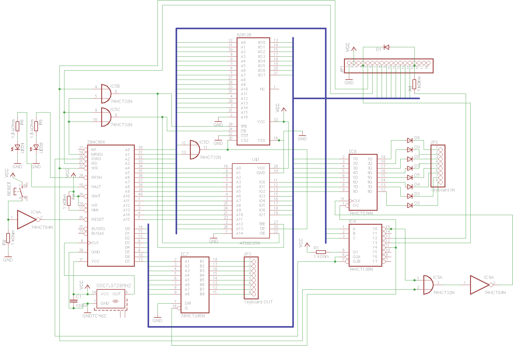
Curcuit of the Z80 SBC with connectors for TFT and keyboard.
Technology and leds
All Chips are in CMOS and HCT technology respectively. I have added some LEDs to see if the machine is working and how it is working. These are low current that only need 2 mA so that it works without additional driver or transistors. In the photo above more LEDs can be seen as in the circuit. I did not add them to the circuit for simplicity, they are simply connected to the data and address bus like the two shown in the circuit.
system clock
I utilise a 7.3728 MHz oscillator which is easier than a crystal. Even if the Z80 is the 6 MHz version the system is absolutely stable. The additional speed is needed to use the TFT at an adequate speed since displaying a single pixel needs many clock cycles. At this clock frequency and the TFT driver I wrote (and is described below) startup takes round about 0.5 seconds.
On the photo a second clock generator is shown that generates a frequency of ~28 Hz. This is useful in combination with the LEDs to see if all pins are connected correctly and data is transferred. To connect it to the CPU just connect it to CLK of the Z80.
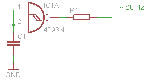
This circuit generates a clock frequency of ~28 Hz.
However, at this frequency nothing else than blinking LEDs happens, but this looks somehow beautiful ;-). Please note that the LEDs on the address bus not only show the addresses of the instruction fetch and data transfer from and to RAM but also the DRAM refresh (even if I only added SRAM), so not everything is an address that is encoded in the program in ROM. See also this very simple Z80 test.
I/O Ports
As usual a circuit is needed to decode the address used in IN and OUT commands to single pins, to which the chip select pins of the peripheral devices can be connected. Here a 74HCT138 is used for this purpose. It is connected to the address pins A5, A6 and A7, such that the port pin can be calculated by the formula Address/2^5 (e.g. port address 0x80 is port pin 4).
Power Supply
As can be seen in the picture, 4 (rechargeable) batteries are enough to run the system. I use rechargeable ones not only to save the environment but also since they have only 1.2V, so 4 give me 4.8V. When they are fully charged it is 5.5V, but that seems to be ok. Also a lower voltage seems to be no problem.
Keyboard
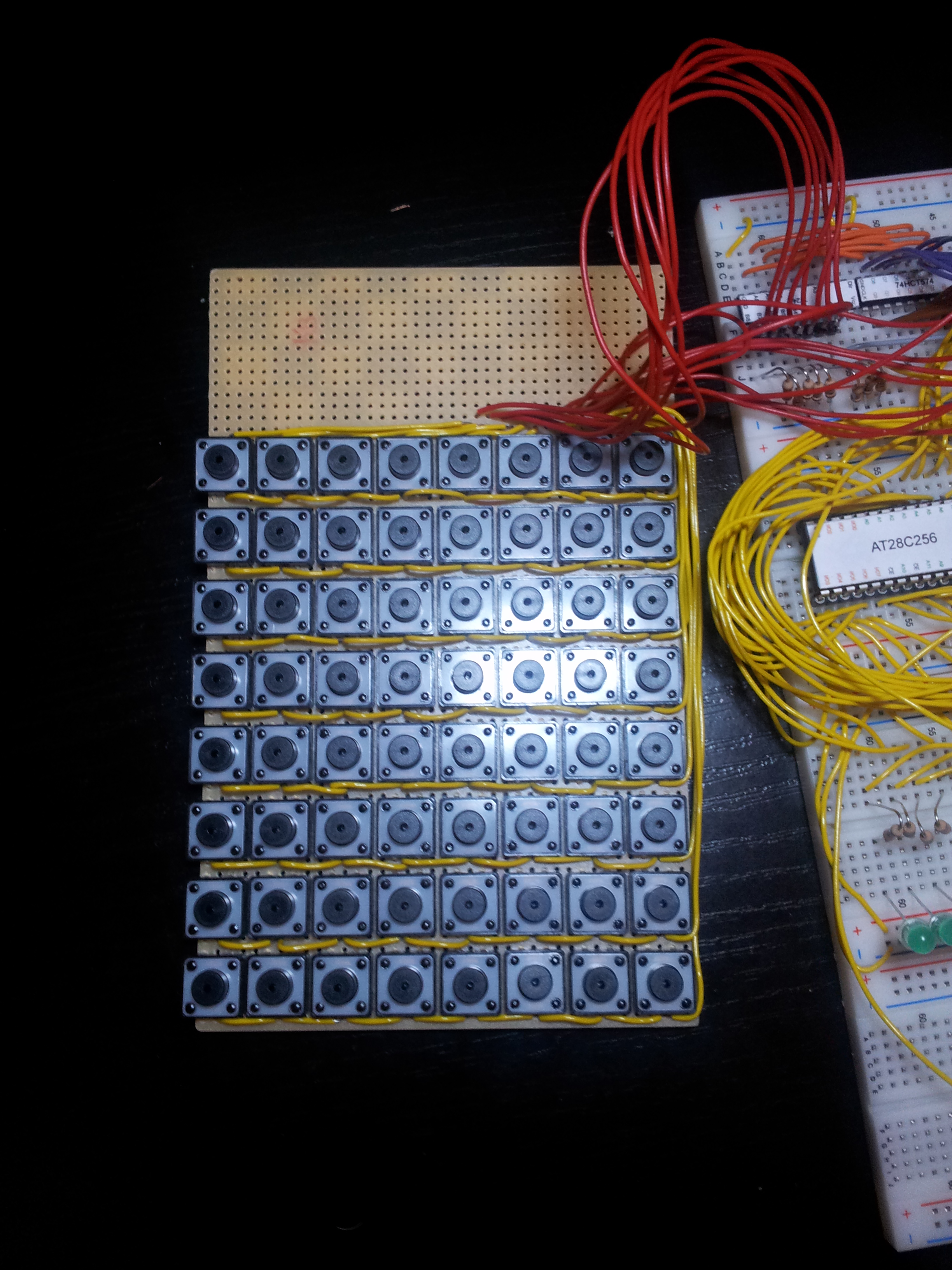
DIY keyboard with 64 keys
The keyboard consists of 64 keys which all can be pressed simultaneously. To be able to read out so much keys they are arranged in 8 lines with 8 columns.
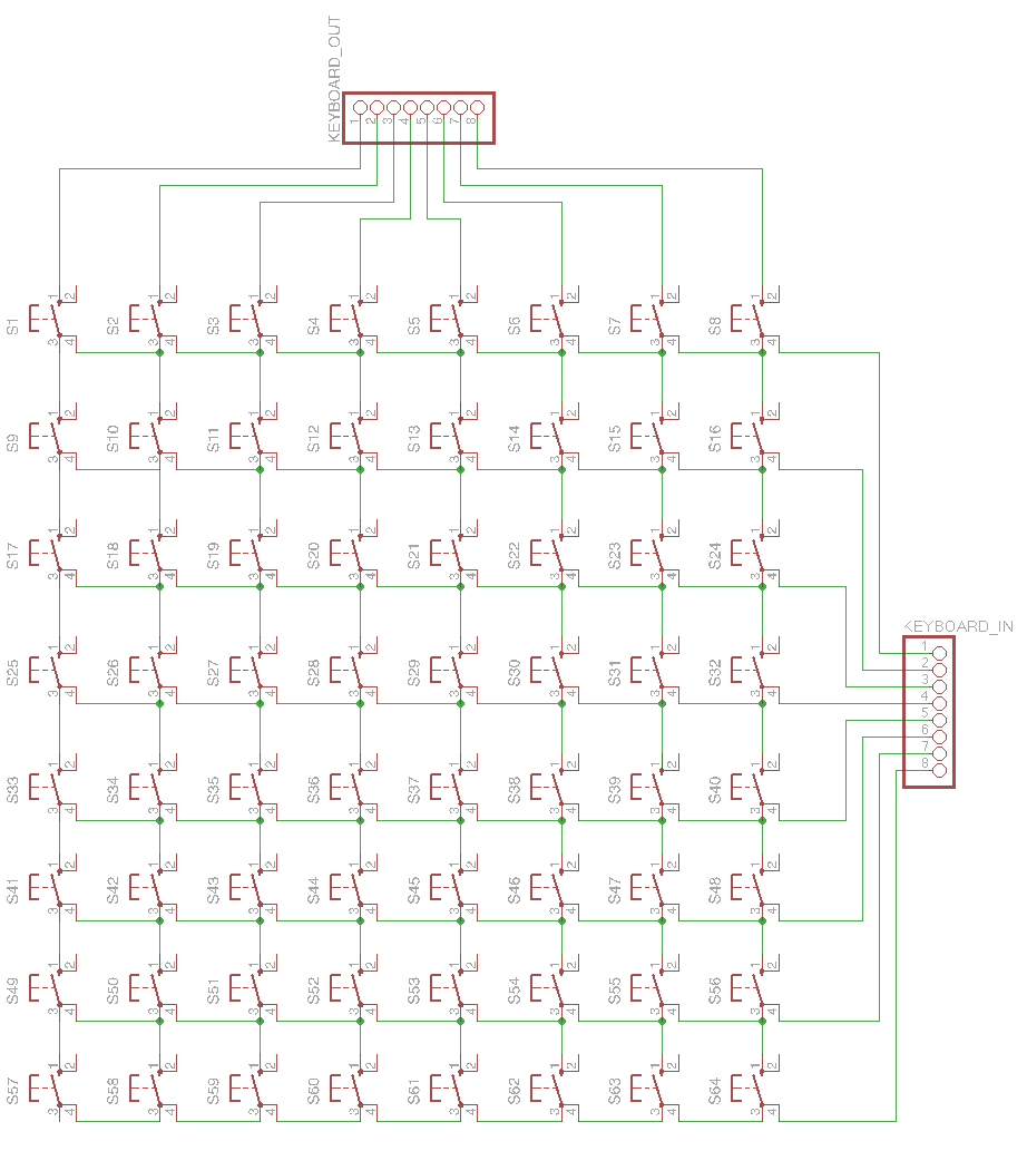
Curcuit of the keyboard.
As can be seen in the circuit, each line can be powered separately, such that the 8 keys can be read out separated from the other lines. To do so, corresponding bit in register 74HCT574 is set (all other bits are 0) by writing to port 0x0 and afterwards the pressed keys in that line are read by reading from port 0x80. To avoid a short cut when a key is pressed, 4148 diodes are utilized. The output of the keyboard is seperated from the bus by a 74HCT245.
A description of the software using this keyboard can be found below in the software section.
ILI9325 based tft
There are many ways to display data. I do not want a microcontroller or another chip that is better than the Z80 to drive the display. The older Sinclair machines create the graphic output with the Z80, but this slows down the machine and needs a lot of parts, so also not really an option.
So I searched for a cheap LCD. I’ve found on eBay some TFT displays with the size of a mobile phone displays that are cheaper than 16×2 or similar text LCDs. Some of them have the ILI9325 controller and therefore are easy to connect to an Arduino or RasPi. Here is the one I have bought. It also has a touch screen but this is not (yet) used in this project.
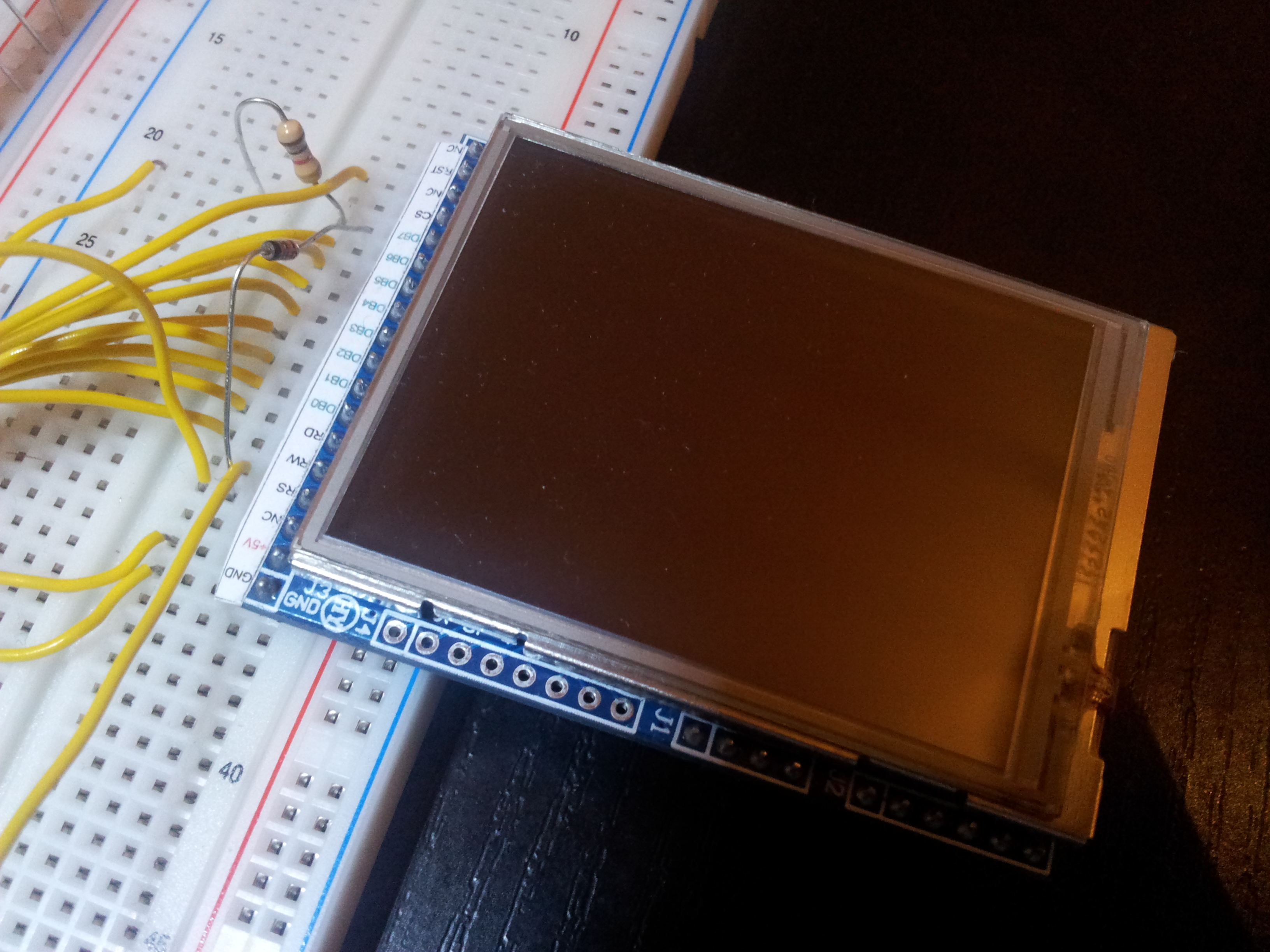
ILI9325 based 2.4″ TFT with 320×240 and 262k colors. It is mounted on a breakout board.
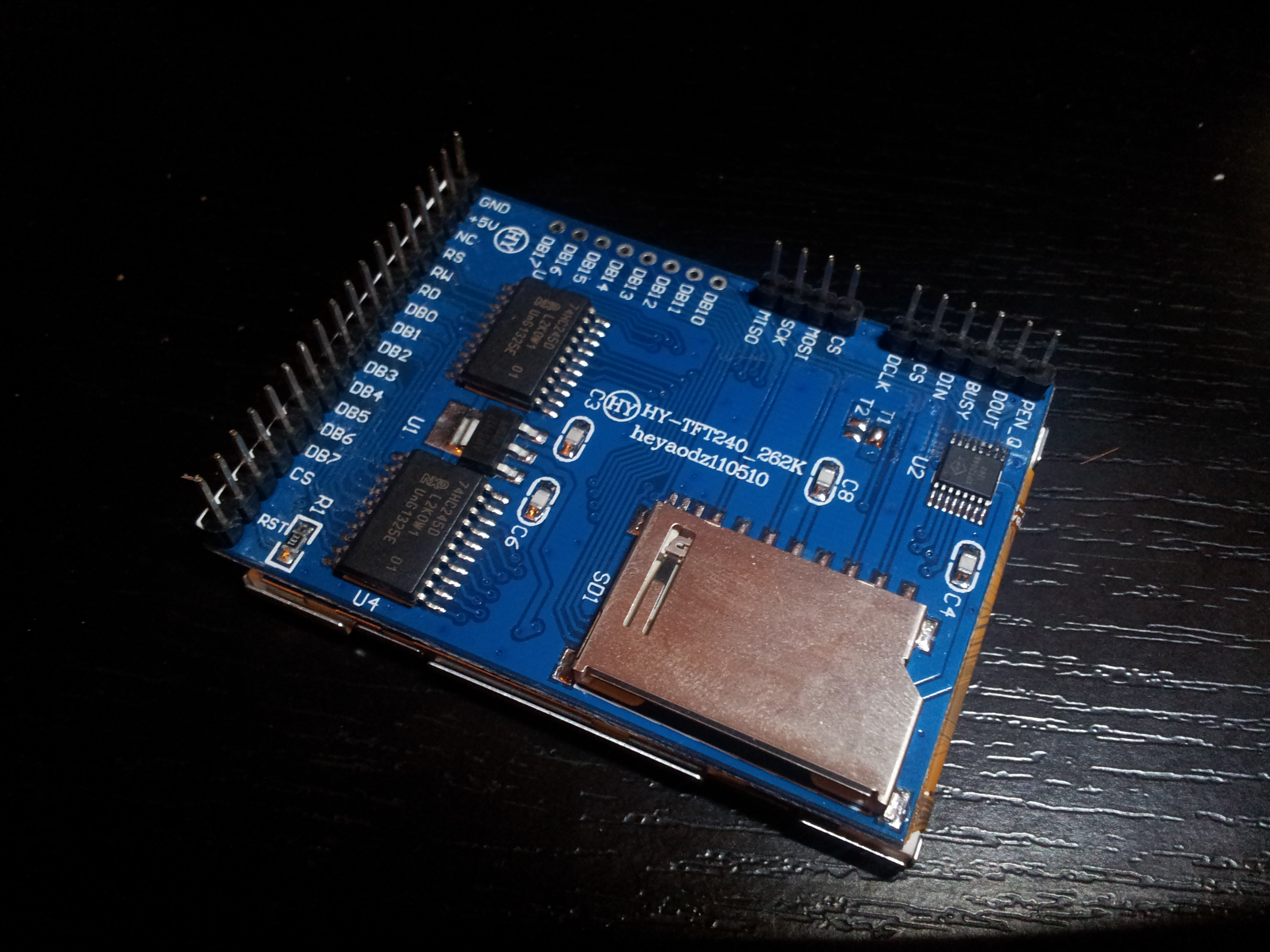
The bottom of the breakout board.
As you can see in the images, the TFT with the controller is mounted on a breakout board. When you search the web or eBay for such a display you will find many different breakout boards with different pin layouts. I chose this one since the connector is perfect for an i80 8 bit bus. It is even better to connect this one to a Z80 bus than to a microcontroller or RasPi, since some of the i80 bus pins must be “emulated” by the microcontroller, which is time consuming. Here is a pin description:
- /RS: Register select (active low). 1 = Control register, 0 = Status Register
- /RW: Write (active low).
- /RD: Read (active low).
- DB0 … DB7: Data bus.
- /CS: Chip select (active low).
- /RST: Reset (active low).
On other breakout boards the pin naming is maybe different, but the function is basically the same. Please note that the pin naming on the breakout board is not correct, since it does not distinguish between active high and active low. There are also pins for SPI and the touch screen interface, but they are not used here. Another advantage of this breakout board is that the logic level is 5V, whereas normally ILI9325 is a 3.3V controller.
As can be seen, the pins fit perfectly to the Z80. The /RW, /RD, /CS and data bus pins can directly be connected to the MCU and the /RST pin can directly be connect to the reset button. The /RS is used here to select the control or data register, so it is advisable connect this pin and the /CS to the 74HCT138 (the port demultiplexer) such that there is a control port and a data port.
A description of the software controlling the TFT can be found below in the software section.
Construction
Some hints for easier construction.
Bill of materials and retailer
Most parts are from a german retailer called Reichelt, but they are common, so you should find a retailer in your country. If not, ebay also has most of them, especially the Z80. The display can be bought from different ebay seller for ~8 Euro. Just search for ILI9325 and compare the photos. Sometimes you will find a cheaper offer in a different currency. The keys are from another german retailer called Pollin who currently sales a bag of 400 keys for ~10 Euro.
Labels
For easier wiring I recommend to stick labels onto the chips:
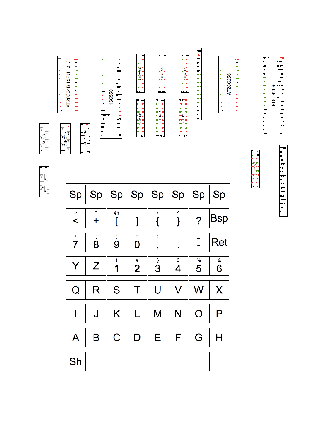
File containing labels for chips and the keyboard.
You can download the OpenOffice.org document to be able to create your own labels. These files do not contain labels for all chips. You can find more labels here.
WIRING
I noticed that the selection of the wires is crucial. I ordered some cheap wires for breadboards from an eBay seller and they are absolutely unusable. The contacts seem to be loose and exchanging one of the wires shown in the picture with one from the prepared wires makes the circuit unusable. So if your SBC does not work, check the wires, maybe you have to use others. I use simple bell wires which are perfect for this breadboards since skinning is all you have to do to insert them.
EEPROM SOCKET
Female pin header for the EEPROM so no force must be exerted.
Writing the EEPROM with a new software version must be done frequently, so I do not push it into the beard directly. I use female pin header as an EEPROM socket since I do not have to push it strongly into the board. In such a header it has contact without force.
WRITING EEPROM
For writing the EEPROM I have bought a cheap programmer on ebay called Top 853. But be prepared, it is cheap. As stated on the product page, it supports only WinXP. I am not able to use it with a newer OS, so I had to setup a virtual machine for this programmer. Also inserting the chip is somehow tricky. Sometimes the software reports that some pins of the chip do not have contact, then I have to reinsert it again and then it works mostly. So, not the best programmer, but it is cheap and works.
Software
To have something useful I adapted the Microsoft BASIC 4.7 modified by Grant Searle to this SBC. I have added code for the keyboard and the display which I will explain in the following. It is written for TASM, so maybe the syntax is a bit different to the assembler your are familiar with. Before I explain the details of the implementation here is the result.
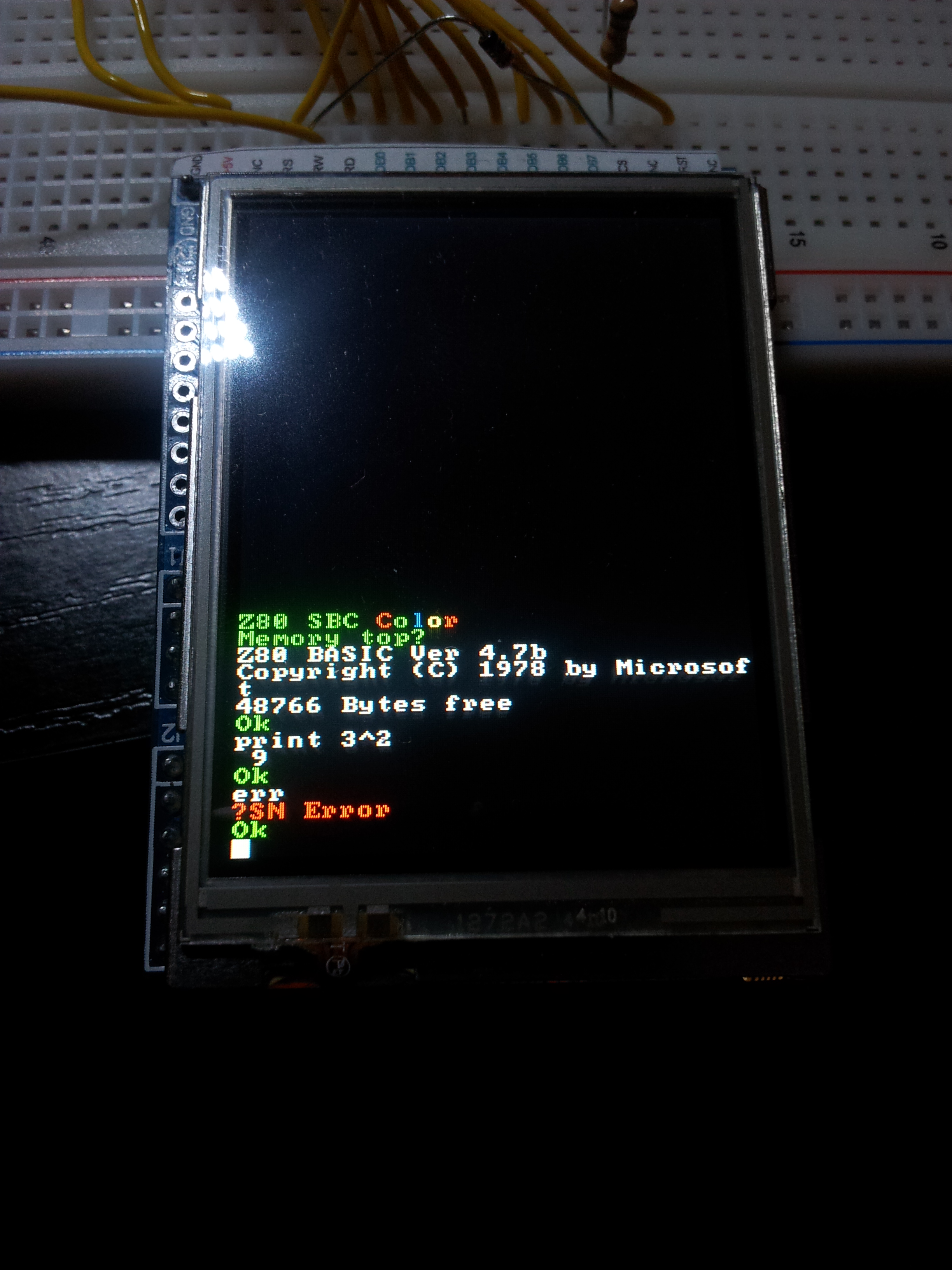
Microsoft BASIC 4.7 running on the SBC.
Since I have a color TFT, I have added some code to get a colorful BASIC. You can find the source code etc. in the download section at the end of this article.
ILI9325 Based TFT
Before the TFT can be used it must be initialized by sending some bytes. The exact meaning can be found in the datasheet of the ILI9325.
            LD        B, 50
            CALL      WAIT
            TFTCMD(   00FFH, 0001H)
            TFTCMD(   00F3H, 0008H)
            LD        BC, 00F3H
            CALL      WRCMD
            TFTCMD(   0001H, 0100H)
            TFTCMD(   0002H, 0700H)
            TFTCMD(   0003H, 1030H)
            TFTCMD(   0008H, 0207H)
            TFTCMD(   0009H, 0000H)
            TFTCMD(   0010H, 0000H)
            TFTCMD(   0011H, 0000H)
            TFTCMD(   0012H, 0000H)
            TFTCMD(   0013H, 0000H)
            LD        B, 50
            CALL      WAIT
            TFTCMD(   0010H, 1290H)
            LD        B, 50
            CALL      WAIT
            TFTCMD(   0011H, 0227H)
            LD        B, 50
            CALL      WAIT
            TFTCMD(   0012H, 001BH)
            TFTCMD(   0013H, 1100H)
            TFTCMD(   0029H, 0019H)
            LD        B, 50
            CALL      WAIT
            TFTCMD(   0030H, 0000H)
            TFTCMD(   0031H, 0107H)
            TFTCMD(   0032H, 0000H)
            TFTCMD(   0035H, 0203H)
            TFTCMD(   0036H, 0402H)
            TFTCMD(   0037H, 0000H)
            TFTCMD(   0038H, 0207H)
            TFTCMD(   0039H, 0000H)
            TFTCMD(   003CH, 0203H)
            TFTCMD(   003DH, 0403H)
            TFTCMD(   0050H, 0000H)
            TFTCMD(   0051H, 00EFH)
            TFTCMD(   0052H, 0000H)
            CALL      CLEAR
            TFTCMD(   0053H, 013FH)
            TFTCMD(   0060H, 0A700H)
            TFTCMD(   0061H, 0003H)
            TFTCMD(   006AH, 0008H)
            TFTCMD(   0090H, 0029H)
            TFTCMD(   0007H, 0133H)
            LD        B, 50
            CALL      WAIT
            LD        BC, 0022H
            CALL      WRCMD
            LD        B, 50
            CALL      WAIT
TFTCMD is a macro which sends a 16 bit value (the latter value) to a port specified by the first value in a way which the ILI9325 understands:
#DEFINE TFTCMD(cmd,dat) \ LD BC, cmd \ CALL WRCMD \ LD BC, dat \ CALL WRDATA
The subroutines WRCMD and WRDATA writes to the command and data registers of the ILI9325 respectively:
WRCMD:      LD        A, B
            OUT       (LCDCTRL), A
            LD        A, C
            OUT       (LCDCTRL), A
            RET

WRDATA:     LD        A, B
            OUT       (LCDDATA), A
            LD        A, C
            OUT       (LCDDATA), A
            RET
The ILI9325 has a 16 bit interface but it is possible to use it with an 8 bit MCU by sending the two bytes of the 16 bit word by sending two single 8 bit values.
Setting a pixel is also easy. First the coordinate must be specified:
LD        BC, 020H
CALL      WRCMD
LD        BC, (COORDX)
CALL      WRDATA
LD        BC, 021H
CALL      WRCMD
LD        BC, (COORDY)
CALL      WRDATA
Command 0x20 is for setting the x coordinate and 0x21 for setting y. Afterwards the color of the pixel can be set:
LD        BC, (TXTCOL)
CALL      WRDATA
It is not necessary to set the coordinate every time we want to set a pixel. After a pixel is set the coordinate is incremented, as we set this in the initialization. It is possible to disable this and to choose which coordinate is incremented or decremented.
Now we can set single pixels, but the ILI9325 does not have any commands to print characters. It is therefore necessary to implement a charater generator.
First we need a font. On a german forum I have found an archive with some nice fonts in different sizes. You can download the archive directly here. Inside you can find some .asm files containing hex values. I use the 8×8 font such that one 8 bit value represents one line of the charater (1 bit per pixel). So all I need to do is to check bit after bit if a pixel is set and set the pixels on the TFT accordingly.
NEXTLINE:   LD        (COORDX), IX    ; Write to mem for GOTOCOORD
            LD        (COORDY), IY
            CALL      GOTOCOORD       ; Set TFT to coord (IX, IY)
            LD        B, 8            ; Start bit with 7
            LD        C, 80H          ; Inverse counter
LINEOUT:    LD        A, (HL)         ; Load Font+8*Char+Line
            AND       C               ; Extract bit number B
            PUSH      BC
            JR        Z, SKIPPIX      ; Don't set pixel if bit not set
            LD        BC, (TXTCOL)
            CALL      WRDATA
                                      ; Write Data to current register
            JR        NOSKIP
SKIPPIX:    LD	      BC, BLACK
            CALL      WRDATA          ; Write Data to current register
NOSKIP:     POP       BC
            SRL       C
            DJNZ      LINEOUT         ; Next pixel if line not finished
            DEC       E               ; Decrease line counter
            RET       Z               ; If 0 all lines done
            INC       IY              ; Otherwise next line
            INC       HL              ; Also next line (byte) in font
            JR        NEXTLINE        ; And go
Usage
In the current version powering on is not optimized, so it is needed to press reset until everything works as expected. Afterwards “Memory top?” will be displayed. You can answer that by pressing enter. You can find more about the BASIC here as I use the same with only a few modifications. You can also download the full documentation:
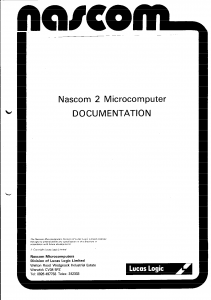
The Basic documentation.
Download
You can download an archive with the assembler source here. It does also contain the TASM assembler and some scripts to assemble them. For the MacOS command file you need a DosBox installation since it uses the same DOS TASM. With the programmer presented above you can directly program the resulting .hex file. If needed you can also create .bin files with TASM.
Here again all the downloads:
Acknowledgements
Many thanks to Grant Searle for his great project and the documentation. This project uses the Microsoft BASIC that was modified by him.
TASM assembler is a partial distribution of the package from Speech Technology Incorporated.