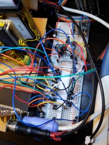
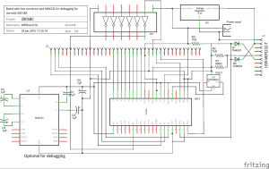
In this article I want to present the WiFi board I have developed for my Z80. It should be no problem to adapt it to different processors as I utilize a 16550 to connect the serial interface of the USR-WIFI232-T to the Z80 bus as you can see in the circuit.
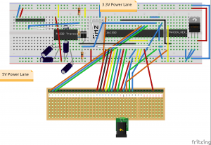
Theo following Image shows the wiring of the bus.
Since the USR-WIFI232-T is driven by 3.3V some kind of level shifting is needed to connect it to the 16C550. Here a simple voltage divider is utilized, build from two resistors for the 5V to 3.3V direction. For 3.3V to 5V a circuit of comparable simplicity is used, consisting of two diodes.
Additionally you can see a MAX232. It is for debugging purposes so you can see the data transferred between the 16C550 and the USR. You can connect TX or RX to the MAX232 to select to part you want to listen to. If you do not want to debug the board, you can just remove the MAX232.
To see how the bus is connected to the CPU please check the main article.


